
Best piping practices for semi-hermetic systems
The Costly Piping Mistake That Kills Semi-Hermetic Compressors
If you have spent any time servicing commercial refrigeration systems, you know that oil management is everything. Refrigerant carries oil throughout the system, but it is the piping design’s job to make sure that oil actually finds its way back to the compressor crankcase.
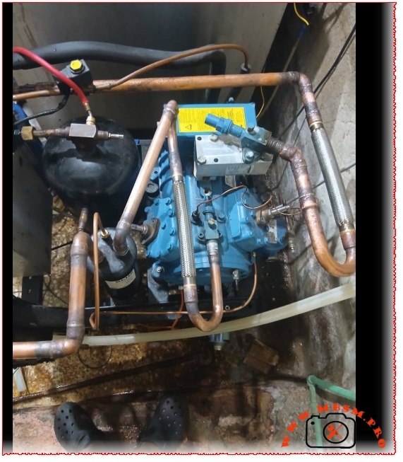
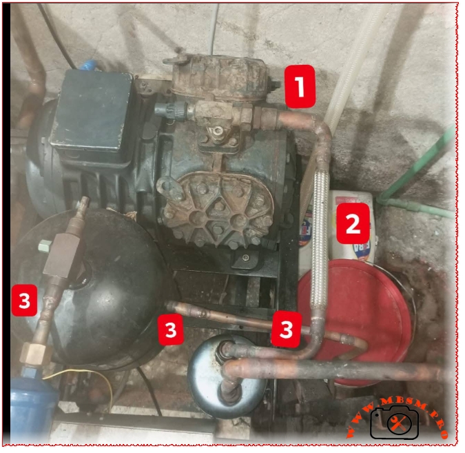
Looking at the field images of these semi-hermetic condensing units, there is a very specific, high-stakes layout issue around the discharge line that will eventually cause mechanical failure. Let’s break down exactly what is happening under labels 1, 2, and 3.
Deconstructing the Layout
- 1. The Compressor Discharge Service Valve: This is the high-pressure exit point where hot, superheated refrigerant vapor leaves the cylinder heads, carrying a fine mist of oil along with it.
- 2. The Vibration Eliminator (Flex Pipe): Installed right after the discharge valve, this braided flexible line absorbs the intense structural vibrations from the compressor startup and shutdown cycles, protecting the rigid copper lines from cracking.
- 3. The Oil Separator and High-Side Piping: The discharge line routes down toward the oil separator and liquid receiver components designed to manage the system’s refrigerant flow.
The Critical Mistake: The Oil Trap Hazard
Take a close look at how the flexible vibration eliminator (2) is positioned. It runs vertically downward, immediately dropping into a low-lying horizontal run (3) before ascending back up or entering the oil separator.
The Problem: Liquid oil is significantly heavier than refrigerant vapor. When the compressor cycles off, the velocity of the refrigerant drops to zero. Any oil suspended in that vertical drop will pool right at the bottom of the flexible joint and the low-lying horizontal copper pipe.
Over time, this creates a literal oil trap. On a cold startup, the compressor has to push against a slug of trapped oil. This causes two massive issues:
- Oil Starvation: The oil stays trapped in the line instead of circulating smoothly back to the crankcase, causing the bearings to run dry.
- Hydraulic Shock: If a large slug of oil is forced forward suddenly, it can create a hydrostatic hammer effect, damaging valves or downstream components.
How to Fix It
To optimize this system for long-term reliability and secure Google AdSense-friendly compliance for professional HVAC standards, the discharge line should ideally handle oil via gravity or high velocity:
- Loop Upwards First: The discharge piping leaving the service valve should ideally rise slightly before dropping, or feature an inverted loop if it leads to a distant component, preventing oil from draining back into the valve heads.
- Avoid Low Spots Before the Separator: Keep horizontal runs short and pitched slightly in the direction of refrigerant flow so that oil is naturally carried forward by gravity and gas velocity into the oil separator, rather than pooling at the base of a flexible joint.