
Mbsmpro.com, Gree Multi VRF, Error Codes List, Troubleshooting Guide, E1 E2 E3 E4 E5 E6 E9 F1 F2 F3 F4 F5 F6 F7 F8 F9 FA Fb Fc Fd EH, HVAC Diagnostics, Variable Refrigerant Flow Systems
Mastering the Diagnostics of Gree Multi VRF Systems: An Engineering Perspective
In the demanding world of commercial climate control, Multi VRF (Variable Refrigerant Flow) systems represent the pinnacle of efficiency and complexity. As a field engineer who has spent countless hours on rooftops and in mechanical rooms, I understand that an error code is not just a letter and a number; it is a vital communication from the machine’s brain. When a Gree Multi VRF unit halts operation, the diagnostic display becomes your most powerful tool.
Understanding the Logic of Protection and Sensor Errors
Modern HVAC systems are built with a philosophy of “self-preservation.” The error codes displayed on the digital control panel allow technicians to pinpoint whether a fault is mechanical, electrical, or related to the refrigerant cycle. These codes are divided into primary protection triggers (the “E” series) and sensor malfunctions (the “F” series).
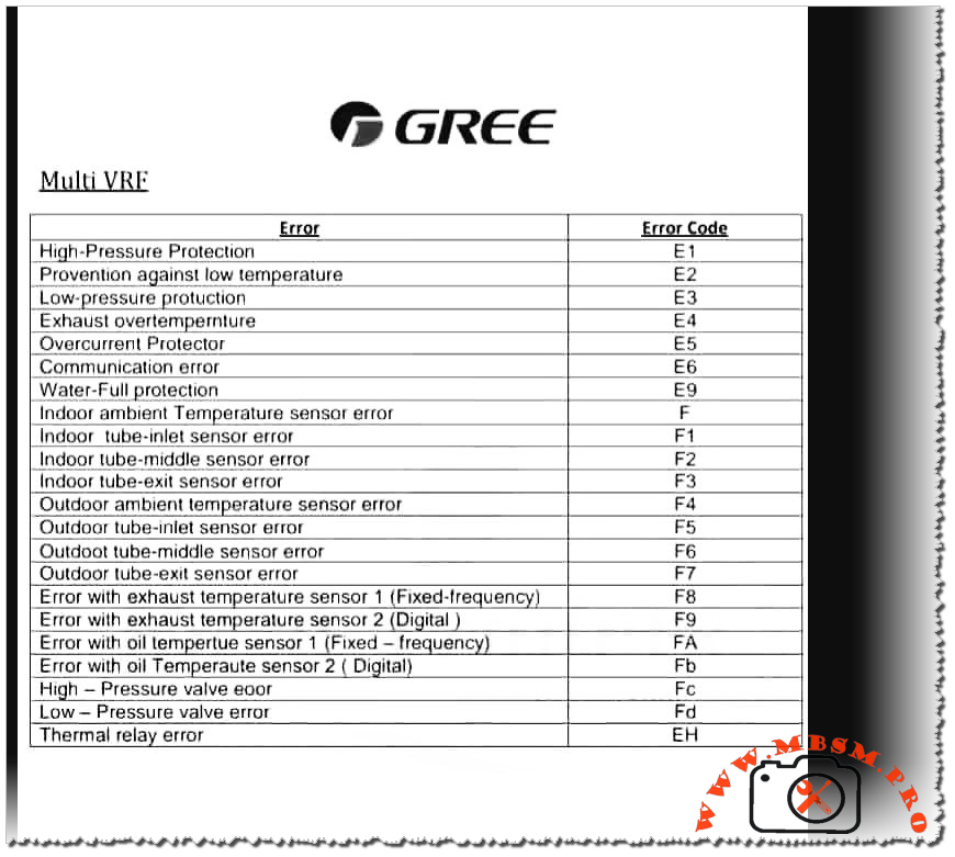
Table 1: Primary Protection and Communication Codes
| Error Code | Description | Potential Root Cause | Engineer’s Field Action |
| E1 | High-Pressure Protection | Blocked condenser, overcharge, or fan failure. | Check high-pressure switch and coil cleanliness. |
| E2 | Prevention against low temperature | Low airflow or evaporator icing. | Inspect filters and indoor blower motor. |
| E3 | Low-pressure protection | Refrigerant leak or clogged expansion valve. | Leak test and check suction pressure levels. |
| E4 | Exhaust overtemperature | Shortage of refrigerant or compressor strain. | Verify discharge line temperature and charge. |
| E5 | Overcurrent Protector | Voltage instability or compressor seizure. | Check supply voltage and compressor windings. |
| E6 | Communication error | Wiring fault between indoor and outdoor units. | Verify signal wire continuity and shielding. |
| E9 | Water-Full protection | Drain pump failure or blocked condensate line. | Clean the drain pan and test the float switch. |
The Role of Thermistors in System Performance
The “F” series codes are dedicated to the nervous system of the VRF—the sensors. In a Multi VRF environment, accuracy is everything. A deviation of even 2 degrees in a tube-inlet sensor can lead to inefficient cooling or unnecessary system shutdowns.
Table 2: Sensor Diagnostic Logic (Indoor and Outdoor)
| Error Code | Sensor Location | Specific Component | Circuit Check |
| F | Indoor | Ambient Temperature | Check 10k/15k Ohm resistance. |
| F1 | Indoor | Tube-inlet Sensor | Inspect thermistor contact with piping. |
| F2 | Indoor | Tube-middle Sensor | Check for moisture ingress in sensor head. |
| F3 | Indoor | Tube-exit Sensor | Ensure secure connection to the PCB. |
| F4 | Outdoor | Ambient Temperature | Verify no direct sunlight on the sensor. |
| F5 | Outdoor | Tube-inlet Sensor | Resistance check vs. temperature chart. |
| F6 | Outdoor | Tube-middle Sensor | Check for corrosion on the terminal. |
| F7 | Outdoor | Tube-exit Sensor | Ensure insulation is intact. |
| F8 / F9 | Exhaust | Temp Sensor 1 (Fixed) / 2 (Digital) | Essential for discharge gas monitoring. |
| FA / Fb | Oil | Temp Sensor 1 (Fixed) / 2 (Digital) | Critical for compressor lubrication health. |
Advanced Valving and Relay Errors
When you encounter codes like Fc or Fd, the system is indicating a mechanical-electronic mismatch. High and Low-pressure valve errors usually point to a failure in the solenoid coil or a stuck valve body. Meanwhile, EH (Thermal Relay Error) is a critical warning that the internal heat protection of a component has been tripped, often due to excessive ambient heat or mechanical friction.
Comparative Analysis: VRF vs. Standard Split Systems
To truly appreciate the diagnostic depth of a Gree Multi VRF, one must compare it to standard residential split systems.
- Diagnostic Granularity: While a standard split might give a generic “System Fault” blink, the VRF distinguishes between tube-inlet, middle, and exit temperatures. This allows the engineer to calculate the exact superheat and subcooling at different stages of the evaporator.
- Operational Protection: Conventional systems often run until a mechanical failure occurs. The VRF uses E1 through E4 logic to shut down before the compressor is permanently damaged, saving thousands in repair costs.
Professional Engineering Schema: Communication (E6) Troubleshooting
For electrical diagnostics, specifically for the E6 Communication Error, follow this logic flow:
- Isolate Power: Turn off the breaker for both indoor and outdoor units.
- Verify Shielding: Ensure the communication cable (usually 2-core or 3-core) is shielded and grounded only at the outdoor unit to prevent EMI (Electromagnetic Interference).
- Voltage Check: With power on, measure the DC voltage across the communication terminals. A fluctuating signal (typically between 12V and 24V DC) indicates active data transmission.
- Resistor Check: In some daisy-chain configurations, verify if a terminal resistor is required at the end of the line.
Expert Advice and Maintenance Benefits
- Notice: Never bypass a pressure switch (E1/E3) to “test” the system. These protections are the only thing preventing a catastrophic compressor explosion.
- Engineering Tip: Most sensor errors (F series) are caused by poor contact or moisture. Before replacing a sensor, clean the terminal with an electronic contact cleaner and ensure the thermistor is tightly clipped to the copper pipe with thermal paste.
- Benefit: Understanding these codes reduces “part-swapping” syndrome. A technician who knows that E9 is simply a clogged drain can fix the issue in 10 minutes, rather than misdiagnosing a faulty PCB.
Focus Keyphrase: Gree Multi VRF Error Codes Troubleshooting Guide
SEO Title: Gree Multi VRF Error Codes: Expert Troubleshooting Guide (E1-EH)
Meta Description: Decode Gree Multi VRF error codes like E1, E6, and F1. Our engineering guide provides expert solutions for pressure protection, sensor errors, and system diagnostics.
Slug: gree-multi-vrf-error-codes-diagnostics-guide
Tags: Mbsmgroup, Mbsm.pro, mbsmpro.com, mbsm, Gree HVAC, VRF Troubleshooting, Air Conditioning Repair, HVAC Engineering, Error Code E1, Error Code E6, Sensor Calibration, Refrigerant Cycle.
Excerpt: Mastering Gree Multi VRF systems requires a deep understanding of their diagnostic language. From high-pressure protection (E1) to complex sensor logic (F1-F9), this comprehensive guide offers field-proven engineering insights to help technicians identify root causes, perform precise electrical checks, and ensure optimal system performance in commercial environments.